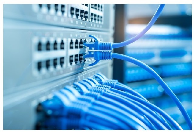
Ethernet switches link devices on a network by transmitting data over their ports. This data is housed in packets identifying each device by its media access control (MAC) address.
An Ethernet switch can process the identifying information in these frames to filter traffic intelligently. It builds a table, or forwarding database, of source addresses that it constantly updates and maintains.
Layer 2
Network technicians toss around the terms Ethernet switch, network switch, hub and router almost interchangeably; however, each device performs a different function on the network. How do Ethernet switches work? Ethernet switches link networks together via transparent bridging. It allows the switch to begin operating without requiring configuration on a network or changes to the devices connected to the switch. Thanks to Fortinet’s networking and security convergence technology, Ethernet may be used as a security infrastructure extension. The device must have a hardcoded physical address called a media access control (MAC) address to connect the device to an Ethernet switch. The MAC addresses are included in the data when a frame travels over the network. The switch looks at the MAC address to determine where to send the frame. The switch also looks at the MAC address to determine which ports are connected to that device. It is done by checking a locally held table. The table includes bit mappings of MAC addresses to port numbers.
As frames are received on a switch port, the software within the switch looks at the source MAC address and adds it to a table of MAC addresses that it constantly updates and maintains. This table referred to as the forwarding database, shows which stations can be reached through each of its ports. For example, if a frame arrives on switch port 6, the switch learns that the destination station is on switch port 2. This information is then used to transmit frames to that station. Entries in the forwarding database will time out if the switch does not see traffic from a given station for some time.
Layer 3
Layer 3 of an Ethernet switch is responsible for routing traffic. It determines which network device a packet is destined for and then sends it to that destination. The switch inspects the packet header and consults a table of MAC addresses and their corresponding physical ports (a CAM or Content Addressable Memory table). The CAM table tells the switch which of its ports to send data to for each particular destination. So, for example, if PC 1 wants to communicate with PC 2 in a faculty VLAN at the university, the switch will determine that the MAC address of PC2 corresponds to port six and will forward the frame to that port. It reduces the number of collisions and allows devices on different VLANs to use the same network segment. A layer three switch also filters broadcasts and other multicast traffic. For example, a switch may suppress frames sent to the broadcast address (all 0s) and thus prevent multiple stations from seeing the same traffic. Another common feature of a layer three switch is the ability to create and manage virtual LANs, or VLANs. It enables network administrators to segment a single physical network into multiple logical networks that can communicate with each other while reducing the amount of data traveling between them.
Layer 4
Ethernet switches offer a simple, cost-effective way to connect devices in your organization to a local area network. They provide a more stable connection than wireless options and come in many different speeds to suit your needs. Many choices are available today, from basic unmanaged network switches offering plug-and-play connectivity to feature-rich Gigabit Ethernet switch solutions. At the data link layer, an Ethernet switch filters and forwards traffic based on the destination address of each frame. The switch builds a database of addresses as it receives frames. It does this by reading the MAC address of each device connected to a port and adding that information to its list of destinations.
For example, a device with the MAC address of 1s sends a frame to station 15. The switch checks its list of addresses and finds that station 15 is reachable on port 2. The switch then transmits the frame from port two without changing the data or addresses within the frame. The switch also uses its database to determine which ports can receive a frame sent to a multicast address, such as the broadcast address (all 0s). If the switch detects that a frame is being sent to a multicast address, it will send it out to all its ports except the one on which it received it. It is called frame flooding to ensure that all stations receive the broadcast.
Layer 5
The Ethernet frame is the basic data structure that carries information from and to devices on the network. A frame has a specific format that must be adhered to for LAN standards to work properly. Frames carry protocol data as well as addressing and routing information. A switch learns which devices (called stations in the LAN standard) are on which segments by looking at the source addresses of frames it receives on each port. The software in the switch then adds this source addresses to a table that the switch constantly updates and maintains in memory—a sort of forwarding database. The switch selects which of its ports to send a frame to reach a new device when it is introduced to the LAN by consulting its address database. It also learns which switches are the bridges that connect the network by looking at the MAC addresses in each frame received on its uplink ports. When a broadcast packet is sent out to the entire LAN, it must reach every station on the LAN. The switch uses a technique known as “frame flooding” to ensure this occurs by flooding broadcast frames out of all of its ports save the one it received them on. The switch eventually learns the correct port and stops flooding the frame around the LAN.


